The is an analysis of the WPC lamp matrix. And a comparason between refresh Procedure 1 and Procedure 2.
Procedure 2 was introduced in by Williams 1995 and used on all new games and updates to current game from then on. It improves a couple of issues with Procedure 1. Prodominently apparent when using LED lamps. And it is believed that this was discovered during developement of Indianapolis 500. Which uses LED lamps on a dusin lamp matrix positions, which was quite unique.
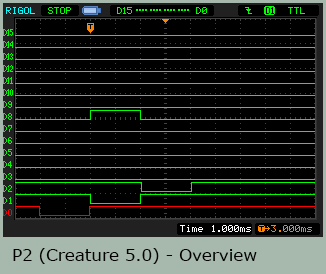
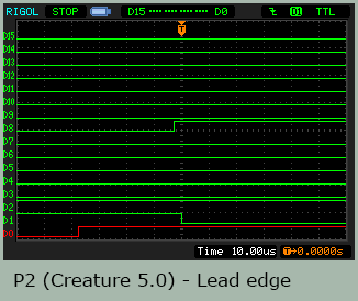
For the rev. 5.0 of Creature From The Black Lagoon it was changed to use Procedure 2.
This analysis is based on a game running Creature From The Black Lagoon rev. L-4 running Procedure 1. A Demolition Man rev. H-6 running Procedure 2. And Creature From The Black Lagoon rev. 5.0 as a retro update revision running Procedure 2.
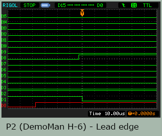
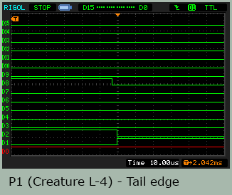
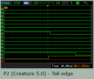
The following are scopes from a logic analyser measuring the three games. D0 is lamp column 1 (active low) with D1 being column 2 and D2 being column 3. D8 is lamp row 1 (active high).
It is worth to note that the probes are connected to the output of the latches – the control logic signals. And not at the lamp matrix signals themselves. The high power lamp lines have ripple noise from shifts in current draw and inductive loads. Plus they are open collector lines, with the column being 18 volts. Stuff that will require a more advanced system for stable reads. Pinball mods etc. wanting to sniff the lamp state – here be warned.
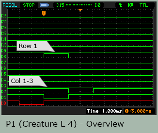
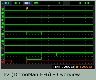
The games are set to lamp 21 test. And it is seen that row 1 is indeed active during the column 2 phase. On this broad time unit (1 ms) all three procedures seem alike. This start to differ once we (100x) zoom in on the lead and tail edges.
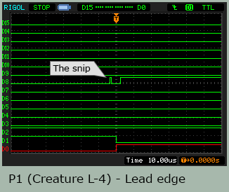
On the lead edge of Procedure 1 it is seen that column stobes are changing state at the same time. With the row state set a little while after this. It is also seen that the row state has a little pre-snip of an active pulse. There are two problems with this. Eventhough the row state is cleared before the column stobe shift, the transistors are not responding fast enough to prevent a current to run at the neighbour column lamp. This may go both ways. But is believed to be mostly present from the now-current row state to the was-active column.
The short snip on the row signal is a whole different issue. It is an error in the programming of the procedure or an error in the hardware logic (the ASIC). Which ever way you want to look at it. But in either case, it can be fixed in the procedure. The snip is not present on all rows, it is not consistent and it is infact unrelated to whether the row maintains the off state through a transition. Or it goes from off to on. The snip will allow a small current to run in a lamp that is to be off. Just at the end of the cycle.
For Procedure 2 it is seen, on lead edge and tail edge, that it has an ordered “column off – row off – pause – new row state – new column strobe” sequence over a substaintially longer interval. And no pre-snip.
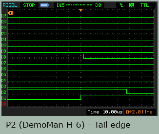
And it can be seen, that the sequences in the updated Creature From The Black Lagoon software and the Demolition Man one are the same.
This YouTube video shows the visible difference on LED lamp (of a certain mark and type, others may differ) of upgrading from Procedure 1 to 2. This, incidently, illustrated on a fourth game title: The Addams Family.